Several years ago here on my blog I presented an algorithm for rotating homogeneous polynomials ( in variables $x$, $y$, and $z$ ) by computing representations of $SO(3)$ on $\mathcal{P}_d$, homogeneous polynomials of degree $d$. These representations are matrices in $SO(\mathcal{P}_d)$ and are rotations of $p \in \mathcal{P}_d$. While writing that post I implemented the recursive algorithm in Python, but never visually demonstrated the rotation of harmonic homogeneous polynomials by representations on $\mathcal{P}_d$. Well, I finally got around to doing just that.
While chatting with my son about how to determine all the factors of an integer he (or maybe my wife) said 9 must be a factor because the digits of the integer sum to 9. Which really surprised me. I don’t recall learning this fact in school. Which I can only blame on my poor American education…
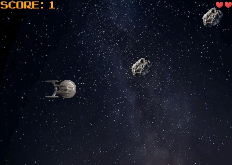
Example game play was captured using a gif maker from
GIPHY.
I made a game!
Maybe re-made is a better description. I coded my own multithreaded version of Asteroids, the classic arcade game. Following the link takes you to the GitHub repo of the game.
Derivations of the perspective projection matrix, whether in books or on the web, always feel either overly complicated or completely lacking in detail–sometimes the perspective projection matrix is just stated without much explaination. In surveys of image projection, that is projection of a 3D scene to 2D, orthographic projection is presented as a contrasting method without relation to perspective projection.
... read more
Given a 3D scene in world coordinates, how does an image of the scene form in the camera, and how do 3D scene points project to the image plane? The short answer to the later question is the camera matrix. And this short note is devoted to deriving the camera matrix. First some mathematical preliminaries.
... read more
Under the guise of rotating solid spherical harmonic functions, I want to investigate the computational aspects of representing rotations of homogeneous polynomials. The connection being that harmonic homogeneous polynomials are solid spherical harmonics. My goal in this note is to rotate solid homogeneous polynomials ( in variables $x$, $y$, and $z$ ) by computing representations of $SO(3)$ on \(\mathcal{P}_d\), homogeneous polynomials of degree $d$. One nice aspect of computing representations of $SO(3)$ is that only algebra is required. Differential equations typically used to describe/derive spherical harmonics make no appearance in what follows.
... read more
is the area form of $S^n$, in terms of its coordinate functions. While trying to understand this formula, I was reminded of the cross product formula, which is an alternating sum of determinants. Well, sure, alternating forms like \(\Gamma_i = dx_1 \wedge \cdots \wedge \widehat{dx_{i}} \wedge \cdots \wedge dx_{n+1}\) are really determinants in disguise. Suppose $v_1, \ldots,v_n$ are tangent vectors at some point on $S^n$. Individually, 1-forms $dx_{j}(v)$ are linear functionals and act on tangent vectors $v \in T_{p}S^n$. Essentially, $dx_{j}(v_k )$ is a portion of the derivative $Dx_j$ in the $v_k$ direction; the directional derivative. Alternatively, it is the action of $v_k$ on coordinate $x_j$. I summarize these two descriptions below.
... read more